
These are the CAN messages that are sent or may be sent by the BMS, and the ones that the BMS may listens to.
The BMS master operates on these fixed parameters:
- CAN communication standard
- 125, 250, 500 kHz (default) or 1MHz {Rev 1.05+}
- Standard addressing (CAN 2.0 A) (11 bits, not extended), except J1939 messages
- Selectable bus termination: included or not
This BMS master places the following messages on the CAN bus:
- A subset of the Standard Traction Pack Messages
- A control message for a Brusa charger
- Messages for the Elithion display
- Data dump of all cell data (optional)
This BMS master places on the CAN bus the applicable subset of the Standard Traction Pack Messages.
Notes:
- Period: 1 s
- Multi-byte values are big-endian: the MSB (Most Significant Byte) is in the lower numbered data byte (the left most byte in the following tables)
- The ID of the 1st message is programmable; the other messages use IDs following the 1st ID
| ID
| Bytes
| Byte 0
| Byte 1
| Byte 2
| Byte 3
| Byte 4
| Byte 5
| Byte 6
| Byte 7
|
| Progr.
| Default
|
| ID0+0
| 0x620
| 8
| "Elithion" (0)
|
| ID0+1
| 0x621
| 8
| "2CN " + Rev level (0)
|
| ID0+2
| 0x622
| 7(20)
| State (1)
| Timer (2)
| Flags (3)
| Fault code (4)
| Level faults (5)
| Warnings (21)
|
|
| ID0+3
| 0x623
| 6
| Pack voltage (6)
| Min Vtg (7)
| Min Vtg # (8)
| Max vtg (7)
| Max Vtg # (8)
|
|
| ID0+4
| 0x624
| 6
| Current (9)
| Charge limit (10)
| Discharge limit (10)
|
|
| ID0+5
| 0x625
| 8
| Batt. energy in (11)
| Batt. energy out (11)
|
| ID0+6
| 0x626
| 7(15)
| SOC (12)
| DOD (13)
| Capacity (14)
| 0x00
| SOH (15)
|
|
| ID0+7
| 0x627
| 6
| Temperature (16)
| -
| Min tmp (17)
| Min tmp # (8)
| Max tmp (17)
| Max tmp # (8)
|
|
| ID0+8
| 0x628
| 6
| Pack resistance (19)
| Min res (20)
| Min res# (8)
| Max res (20)
| Max res# (8)
|
|
- ASCII, starting from rev 0.97. Rev level: F1.04 = Harware rev F, Software rev 1.04
- State of system
- Bit 4: Relay fault
1 = while attempting to turn on the contactors, the tests detected a fault, and the contactors were turned off
- Bit 3: Contactor K3 is on
1 = K3 LED is on and K3 output is grounded in COILS connector on BMS master; K3 output of HVFE is grounded
- Bit 2: Contactor K2 is on
1 = K2 LED is on and K3 output is grounded in COILS connector on BMS master; K2 output of HVFE is grounded
- Bit 1: Contactor K1 is on
1 = K1 LED is on and K3 output is grounded in COILS connector on BMS master; K1 output of HVFE is grounded
- Bit 0: Fault state
0 = OK; 1 = BMS master is in the Fault State
The BMS master enters into the Fault State after a fault has lasted for some time (the "Fault Delay Time"), except for "Tripped Interlock", which causes an immediate fault.
The fault must be cleared manually (by cycling the power off and on, or through the GUI)
If configured for normal polarity, 1 = FLT LED is on and FLT output is grounded;
if configured for reversed polarity, 1 = FLT LED is off and FLT output is open.
The FLT LED and output are not affected if they are configured to work as a Warning output instead of a Fault output.
- Power up time [s]; after 65535 s, it overflows back to 0
- Byte of flags:
- Bit 7: The Fan is on
The FAN LED is on and the FAN output is grounded
- Bit 6: The LLIM is set: cannot discharge
By default: 1 = the LLIM LED is on and the LLIM output is grounded
If so configured: 1 = the LLIM LED is off and the LLIM output is open
- Bit 5: The HLIM is set: cannot charge
By default: 1 = the HLIM LED is on and the HLIM output is grounded
If so configured: 1 = the HLIM LED is off and the HLIM output is open
- Bit 4: There is a CAN contactor request
CAN ID, byte, bit and polarity are configurable)
- Bit 3: There is a hard wire contactor request
Configurable whether active low / open or active high
- Bit 2: The interlock is tripped
Configurable whether tripped = input is open or tripped = input is closed
- Bit 1: There is power from the load
Vl power input of the BMS master
- Bit 0: There is power from the source
Vs power input of the BMS master
- Fault code, stored:
- Driving off while plugged in
- Interlock is tripped
- Communication fault with a bank or cell
- Charge overcurrent
- Discharge overcurrent
- Over-temperature
- Under voltage
- Over voltage
- No battery voltage
- High voltage B- leak to chassis
- High voltage B+ leak to chassis
- Relay K1 is shorted
- Contactor K2 is shorted
- Contactor K3 is shorted
- Open K1 or K3, or shorted K2
- Open K2
- Excessive precharge time
- EEPROM stack overflow
- Loss of CAN from HVFE {Rev 1.27}
- Level fault flags:
- Bit 7: Over voltage
- Bit 6: Under voltage
- Bit 5: Over-temperature
- Bit 4: Discharge overcurrent
- Bit 3: Charge overcurrent
- Bit 2: Communication fault with a bank or cell
- Bit 1: Interlock is tripped
- Bit 0: Driving off while plugged in
- Total voltage of pack [V], unsigned, 0 to 65 kV, as the sum of all cell voltages; {in rev 1.05 and above, if available, measured directly by the HVFE}
- Voltages [100 mV] of least charged cell and most charged cell, 0 to 25.5 V {30 s average voltage in revs 1.04 and below}
- ID of the cell that has the lowest / highest voltage / temperature / resistance. 0 to 255
- Pack current [A], signed*, positive out of pack, -32kA to + 32kA, averaged over 1 s
- Maximum current acceptable (charge) or available (discharge), unsigned, 0 to + 65kA [A]
- Total energy in or out of battery, since manufacture. Unsigned, overflows back to 0 [kWH]
- State Of Charge [%], unsigned, 0 to 100. When deeply discharged, its value does not go below 0
- Depth Of Discharge [AH], unsigned, 0 to 65 kAH. When deeply discharged, its value may exceed the actual capacity's value
- Actual capacity of pack [AH], unsigned, 0 to 65 kAH
- State Of Health [%], unsigned, 0 to 100. 100 % = all OK {Starting from rev 0.97; in older revs only 6 bytes are sent in this message}
- Average pack temperature [°C], signed*, -127 °C to +127 °C
- Temperatures [°C] of coldest and hottest sensors, signed*, -127 °C to +127 °C
- -
- Resistance [100 micro-ohm] of entire pack, unsigned, 0 to 6553.5 milliohm
- Resistances [100 micro-ohm] of lowest and highest resistance cells, unsigned, 0 to 25.5 milliohm
- Warning flags: {starting from rev 0.97; in rev < 0.97 the number of bytes was 6}
- Bit 7 (0x80): isolation fault {Rev 2.02 and up}
- Bit 6 (0x40): low SOH
- Bit 5 (0x20): hot temperature
- Bit 4 (0x10): cold temperature
- Bit 3 (0x08): discharge overcurrent
- Bit 2 (0x04): charge overcurrent
- Bit 1 (0x02): high voltage
- Bit 0 (0x01): low voltage
*) Signed = 2's complement: 0xFF = -1, 0x00 = 0, 0x01 = 1
Custom messages use an 11-bit ID, 0 to 8 data bytes, 10 ms to 25 s rate, and the data may include any combination of any parameter.
See the custom message set-up instructions for more information.
This BMS master places on the CAN bus a message for Elithion hardware:
Notes:
- Period: 2 messages every 100 ms, separated by 10 ms
- Length: 3 bytes
| ID
| Item
| Byte 0: Address
| Byte 1: Mask
| Byte 2: Data
|
| Bit 7
| Bit 6
| Bit 5
| Bit 4
| Bit 3
| Bit 2
| Bit 1
| Bit 0
|
| 0x680
| Display LEDs
| 0x1E
| 0xFF
| -
| -
| 0 = Fault
| 0 = Current limited
| 0 = Powered by load
| -
| 0 = Contactors on
| 0 = Powered by source
|
| Display SOC bar
| 0x25
| 0xFF
| 0x00 to 0x64 - 0 to 100%
|
| HVFE
| 0x48
| 0xFF
| -
| 1 = Drive Precharge switch
| 1 = Drive SW- switch
| 1 = Drive SW+ switch
| 1 = Drive relay K3
| 1 = Drive relay K2
| 1 = Drive relay K1
| 1 = Fault
|
The BMS can be programmed to dump the data from all the cells onto the CAN bus.
Tha data consists of a set of messages, once a second.
- The first message gives all the readings of a particular cell, and rotates through each cell sued, one cell per second
- The other messages give the voltage readings of all the cells actually used
- The number of messages ranges from 1 (if 1 to 8 cells are used) all the way to 32 (if 249 to 255 cells are used)
The format of the data dump is:.
- Rate: a burst every 1 second, with individual messages generated every 10 ms
- Length: 8 data bytes
- Units:
- Voltages are in 10 mV, offset by 2 V (So, 0x00 = 2 V, 0x10 = 2.16 V...)
- Temperatures are in °C, offset by 0x80 (So, 0x80 = 0 °C, 0x81 = 1 °C, 0x7F = -1 °C)
- Resistances are in 100 µΩ (So, 0x01 = 100 µΩ)
- Status; each bit is a flag:
- 1 = the voltage reading from this cell board is OK
- 1 = the temperature reading from this cell board is OK
- 1 = the resistance reading from this cell board is OK
- 1 = the cell board reports its load is on
- 1 = the cell board reports a voltage sensor fault
- 1 = the cell board reports a temperature sensor fault
- 1 = the cell board reports a resistance calculation fault
- 1 = the cell board reports a load fault
| ID
| Data 0
| Data 1
| Data 2
| Data 3
| Data 4
| Data 5
| Data 6
| Data 7
| Notes
|
| ID+0
| Cell number
| Voltage
| Temperature,
all the time
| Resistance
| Status
| 5
| 5
| 5
| Up to Rev 0.96
|
Temperature
when balancing
load is off
| Resistance
| 5
| 5
| 5
| Rev 0.97 to 1.06
|
| Status
| 0
| 0
| Rev 1.07+
|
| ID+1
| Cell 0 vtg
| Cell 1 vtg
| Cell 2 vtg
| Cell 3 vtg
| Cell 4 vtg
| Cell 5 vtg
| Cell 6 vtg
| Cell 7 vtg
|
|
| ID+2
| Cell 8 vtg
| Cell 9 vtg
| Cell 10 vtg
| Cell 11 vtg
| Cell 12 vtg
| Cell 13 vtg
| Cell 14 vtg
| Cell 15 vtg
|
| ID+3
| Cell 16 vtg
| Cell 17 vtg
| Cell 18 vtg
| Cell 19 vtg
| Cell 20 vtg
| Cell 21 vtg
| Cell 22 vtg
| Cell 23 vtg
|
| ID+4
| Cell 24 vtg
| Cell 25 vtg
| Cell 26 vtg
| Cell 27 vtg
| Cell 28 vtg
| Cell 29 vtg
| Cell 30 vtg
| Cell 31 vtg
|
| ID+5
| Cell 32 vtg
| Cell 33 vtg
| Cell 34 vtg
| Cell 35 vtg
| Cell 36 vtg
| Cell 37 vtg
| Cell 38 vtg
| Cell 39 vtg
|
| ID+6
| Cell 40 vtg
| Cell 41 vtg
| Cell 42 vtg
| Cell 43 vtg
| Cell 44 vtg
| Cell 45 vtg
| Cell 46 vtg
| Cell 47 vtg
|
| ID+7
| Cell 48 vtg
| Cell 49 vtg
| Cell 50 vtg
| Cell 51 vtg
| Cell 52 vtg
| Cell 53 vtg
| Cell 54 vtg
| Cell 55 vtg
|
| ID+8
| Cell 56 vtg
| Cell 57 vtg
| Cell 58 vtg
| Cell 59 vtg
| Cell 60 vtg
| Cell 61 vtg
| Cell 62 vtg
| Cell 63 vtg
|
| ID+9
| Cell 64 vtg
| Cell 65 vtg
| Cell 66 vtg
| Cell 67 vtg
| Cell 68 vtg
| Cell 69 vtg
| Cell 70 vtg
| Cell 71 vtg
|
| ID+10
| Cell 72 vtg
| Cell 73 vtg
| Cell 74 vtg
| Cell 75 vtg
| Cell 76 vtg
| Cell 77 vtg
| Cell 78 vtg
| Cell 79 vtg
|
| ID+11
| Cell 80 vtg
| Cell 81 vtg
| Cell 82 vtg
| Cell 83 vtg
| Cell 84 vtg
| Cell 85 vtg
| Cell 86 vtg
| Cell 87 vtg
|
| ID+12
| Cell 88 vtg
| Cell 89 vtg
| Cell 90 vtg
| Cell 91 vtg
| Cell 92 vtg
| Cell 93 vtg
| Cell 94 vtg
| Cell 95 vtg
|
| ID+13
| Cell 96 vtg
| Cell 97 vtg
| Cell 98 vtg
| Cell 99 vtg
| Cell 100 vtg
| Cell 101 vtg
| Cell 102 vtg
| Cell 103 vtg
|
| ID+14
| Cell 104 vtg
| Cell 105 vtg
| Cell 106 vtg
| Cell 107 vtg
| Cell 108 vtg
| Cell 109 vtg
| Cell 110 vtg
| Cell 111 vtg
|
| ID+15
| Cell 112 vtg
| Cell 113 vtg
| Cell 114 vtg
| Cell 115 vtg
| Cell 116 vtg
| Cell 117 vtg
| Cell 118 vtg
| Cell 119 vtg
|
| ID+16
| Cell 120 vtg
| Cell 121 vtg
| Cell 122 vtg
| Cell 123 vtg
| Cell 124 vtg
| Cell 125 vtg
| Cell 126 vtg
| Cell 127 vtg
|
| ID+17
| Cell 128 vtg
| Cell 129 vtg
| Cell 130 vtg
| Cell 131 vtg
| Cell 132 vtg
| Cell 133 vtg
| Cell 134 vtg
| Cell 135 vtg
|
| ID+18
| Cell 136 vtg
| Cell 137 vtg
| Cell 138 vtg
| Cell 139 vtg
| Cell 140 vtg
| Cell 141 vtg
| Cell 142 vtg
| Cell 143 vtg
|
| ID+19
| Cell 144 vtg
| Cell 145 vtg
| Cell 146 vtg
| Cell 147 vtg
| Cell 148 vtg
| Cell 149 vtg
| Cell 150 vtg
| Cell 151 vtg
|
| ID+20
| Cell 152 vtg
| Cell 153 vtg
| Cell 154 vtg
| Cell 155 vtg
| Cell 156 vtg
| Cell 157 vtg
| Cell 158 vtg
| Cell 159 vtg
|
| ID+21
| Cell 160 vtg
| Cell 161 vtg
| Cell 162 vtg
| Cell 163 vtg
| Cell 164 vtg
| Cell 165 vtg
| Cell 166 vtg
| Cell 167 vtg
|
| ID+22
| Cell 168 vtg
| Cell 169 vtg
| Cell 170 vtg
| Cell 171 vtg
| Cell 172 vtg
| Cell 173 vtg
| Cell 174 vtg
| Cell 175 vtg
|
| ID+23
| Cell 176 vtg
| Cell 177 vtg
| Cell 178 vtg
| Cell 179 vtg
| Cell 180 vtg
| Cell 181 vtg
| Cell 182 vtg
| Cell 183 vtg
|
| ID+24
| Cell 184 vtg
| Cell 185 vtg
| Cell 186 vtg
| Cell 187 vtg
| Cell 188 vtg
| Cell 189 vtg
| Cell 190 vtg
| Cell 191 vtg
|
| ID+25
| Cell 192 vtg
| Cell 193 vtg
| Cell 194 vtg
| Cell 195 vtg
| Cell 196 vtg
| Cell 197 vtg
| Cell 198 vtg
| Cell 199 vtg
|
| ID+26
| Cell 200 vtg
| Cell 201 vtg
| Cell 202 vtg
| Cell 203 vtg
| Cell 204 vtg
| Cell 205 vtg
| Cell 206 vtg
| Cell 207 vtg
|
| ID+27
| Cell 208 vtg
| Cell 209 vtg
| Cell 210 vtg
| Cell 211 vtg
| Cell 212 vtg
| Cell 213 vtg
| Cell 214 vtg
| Cell 215 vtg
|
| ID+28
| Cell 216 vtg
| Cell 217 vtg
| Cell 218 vtg
| Cell 219 vtg
| Cell 220 vtg
| Cell 221 vtg
| Cell 222 vtg
| Cell 223 vtg
|
| ID+29
| Cell 224 vtg
| Cell 225 vtg
| Cell 226 vtg
| Cell 227 vtg
| Cell 228 vtg
| Cell 229 vtg
| Cell 230 vtg
| Cell 231 vtg
|
| ID+30
| Cell 232 vtg
| Cell 233 vtg
| Cell 234 vtg
| Cell 235 vtg
| Cell 236 vtg
| Cell 237 vtg
| Cell 238 vtg
| Cell 239 vtg
|
| ID+31
| Cell 240 vtg
| Cell 241 vtg
| Cell 242 vtg
| Cell 243 vtg
| Cell 244 vtg
| Cell 245 vtg
| Cell 246 vtg
| Cell 247 vtg
|
| ID+32
| Cell 248 vtg
| Cell 249 vtg
| Cell 250 vtg
| Cell 251 vtg
| Cell 252 vtg
| Cell 253 vtg
| Cell 254 vtg
| Cell 255 vtg
|
In revisions 0.96 and below, the first 64 cells are shown, and the 1st message scrolls through 255 cells, regardless of the number of cells actually used, for a total of 9 messages.
This BMS master looks on the CAN bus for messages to request that the contactors be turned on.
The format is programmable.
Notes:
- Maximum period: 300 ms (after which it assumes there is no such message on the CAN bus)
Default message:
| ID
| Bytes
| Byte 0
| Byte 1
| Byte 2
| Byte 3
| Byte 4
| Byte 5
| Byte 6
| Byte 7
|
| 0x632
| 8
| Requests (1)
|
|
- 0x00 = request contactors be off; 0x01 = request contactors be on
This BMS master looks on the CAN bus for messages with the battery current from/to the load and the source.
The format is programmable.
Notes:
- Maximum period: 300 ms (after which it assumes there is no such message on the CAN bus)
Default messages:
| ID
| Bytes
| Byte 0
| Byte 1
| Byte 2
| Byte 3
| Byte 4
| Byte 5
| Byte 6
| Byte 7
|
| 0x611
| 8
|
| Source current (1)
|
| 0x633
| 8
| Load current (2)
|
|
- [10 mA], + = into battery, big-endian. Preset for compatibility with Brusa NLG5 charger
- [100 mA], + = out of battery, big-endian
This BMS master looks on the CAN bus for messages from the Elithion Remote HV front end.
Notes:
- Maximum period: 300 ms (after which it assumes there is no such message on the CAN bus)
| ID
| Bytes
| Byte 0
| Byte 1
| Byte 2
| Byte 3
| Byte 4
|
| 0x681
| 5
| Load current (1)
| Source current (1)
| Data (2)
|
| ID
| Bytes
| Byte 0
| Byte 1
| Byte 2
| Byte 3
| Byte 4
| Byte 5
| Byte 6
|
| 0x681
| 7
| Load current (1)
| Source current (1)
| Data (2)
| Pack voltage (3)
|
- [10 mA], + = into battery, big-endian
- Bit 0: 1 = no voltage seen by the HVFE during contactor tests
- 24 to 1250 V, [100 mV], big-endian
PID (Parameter ID) are codes that used to request data and send commands through the CAN bus.
The Lithiumate implements a set of some 1500 codes, that enable you to:
- Get the value of individual parameters
- Clear faults
- You send a PID request to the BMS master through the CAN bus
- The BMS master responds with the data with a different PID message
- The request ID is programmable.
- The response ID is 0x08 more than the request ID
- Data length is 8 data bytes regardless of whether sme or all bytes are actually used (unused bytes are set at 0)
Note that the default CAN request ID changed from rev 1.xx to rev 2.xx, in order to support the Torque application (you can change the ID).
This table lists all the PIDs and the PID CAN IDs.
Through PIDs, you can change the settings in EEPROM.
This spreadsheet has a list of the EEPROM data.
The Lithiumate may be programmed to generate the following messages for the Morey Telematic Trax MT-30 Automotive X-Prize data acquisition system.
Please contact us for instructions on how to turn on this feature: In the classic UI (Ctrl-T in the GUI to get to it), press: H, 6, 6, 3B Tab 20 Enter
| PGN
| Repetition rate
| Data length
| Data page
| PDU format
| PDU specific
| Default priority
| Source Address
| ID
| Byte 0
| Byte 1
| Byte 2
| Byte 3
| Byte 4
| Byte 5
| Byte 6
| Byte 7
|
| 65284
| 10 ms
| 8
| 0
| 255
| 04
| 6
| xx
| 0x18FF04F4
| (n.a.)
0xFFFF
| (n.a.)
0xFFFF
| LSB
| MSB
| LSB
| 0x00
| MSB
|
HV Traction Battery
Voltage (1)
| HV Traction Battery
Current (2)
|
| 65285
| 10 ms
| 8
| 0
| 255
| 05
| 6
| xx
| 0x18FF05F4
| HV Traction Battery
state of charge (3)
| 0x00
| LSB
| 0x00
| MSB
| (n.a.)
0xFFFF
| (n.a.)
0xFFFF
|
HV Traction Battery
temperature (max) (4)
|
- 24 to 4095 [V]; unsigned; 2 bytes; Little-Endian;
- -2047 to 0 to +2047 [A]; signed; 2 bytes, Little-Endian; 12 bits; 4 Most Significant Bits are 0, even for negative current
- 0 to 100 [%]; unsigned; 1 byte;
- -127 to 0 to + 127 [°C]; signed; 2 bytes, Little-Endian; 12 bits; 4 Most Significant Bits are 0, even for negative temperature. Note that without cell boards the temperature is not known, and a default temperature of 25 °C is reported
Where input values are 12-bit values from 0x000 - 0xFFF.
A value of 0xFFxx(3) can also be specified indicating that this parameter us not provided in this packet at this time.
This is to allow multiple controllers to send these packets.
(3)Per SAE J1939-71 (Jan 2009) section 5.1.5 Table 1.
This file is the .dbc for the Lithiumate series of controllers.
| BMS rev
| Default CAN speed
| Byte order
| Read current from charger
|
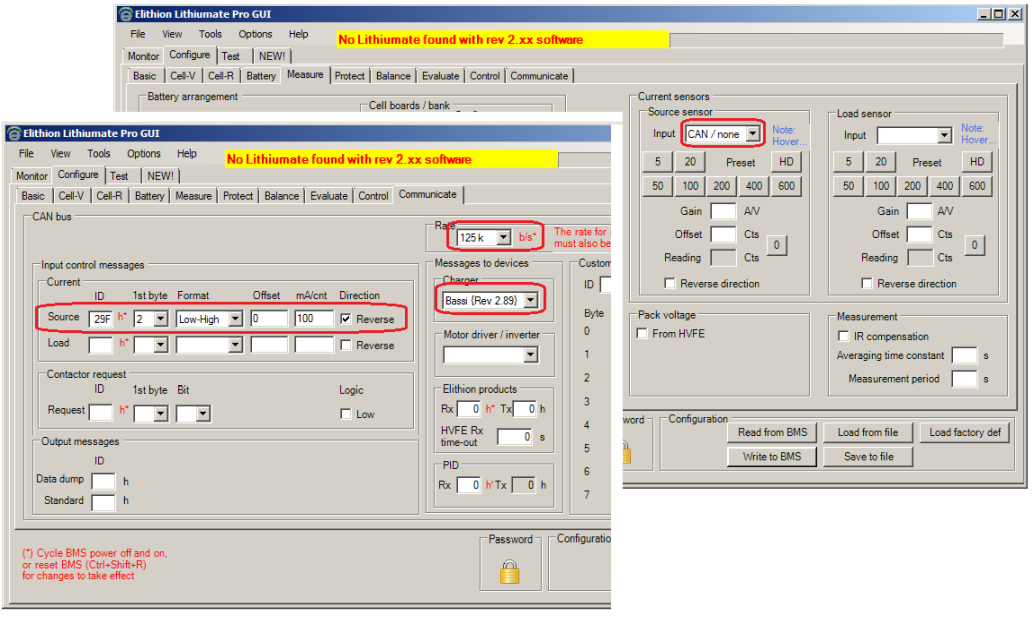
| 2.89+
| 125 kbps *
| Little endian
| Yes
|
*) Both the BMS and the charger can be configured for a different speed
| ID
| Bytes
| Rate
| Byte 0
| Byte 1
| Byte 2
| Byte 3
| Byte 4
| Byte 5
| Byte 6
| Byte 7
|
| 0x284
| 8
| 1 s
| 0x00
| SoC [%]
| 0x00
| 0x00
| CC setting [62.5 mA]
LSB - MSB
| CV setting [62.5 mV]
LSB - MSB
|
| ID
| Bytes
| Time-out
| Byte 0
| Byte 1
| Byte 2
| Byte 3
| Byte 4
| Byte 5
| Byte 6
| Byte 7
|
| 0x29F
| 8
| 2 s
| 0x00
| 0x00
| Actual current [100 mA]
LSB - MSB
| Actual voltage [100 mV]
LSB - MSB
| 0x00
| 0x00
|
Configure the BMS to receive current from the charger: Configure tab / Communications tab / Input Control Messages box / Current box
The Lithiumate interfaces seamlessly with the Brusa NLG5 chargers.
If enabled, the BMS master places on the CAN bus a control message for a NLG5 charger.
Notes:
- Period: 100 ms
- Multi-byte values are big-endian: the MSB (Most Significant Byte) is in the lower numbered data byte (the left most byte in the following tables)
| ID
| Bytes
| Byte 0
| Byte 1
| Byte 2
| Byte 3
| Byte 4
| Byte 5
| Byte 6
| Byte 7
|
| 0x618
| 7
| Flags (1)
| Max IAC (2)
| Max VDC (3)
| Max IDC (4)
|
|
- Control flags. Only 1 bit is used, all others are 0:
- Bit 7: 1 to enable charging; 0 to disable charging
- Maximum current from the AC inlet [100 mA]
- Maximum DC output voltage [100 mV]
- Set to the pack voltage when all the cells are full and balanced (Max cell voltage x number of cells in series)
- Maximum DC output current [100 mA]
By default, the BMS looks for battery current information at the ID that the Brusa uses:
| ID
| Bytes
| Byte 0
| Byte 1
| Byte 2
| Byte 3
| Byte 4
| Byte 5
| Byte 6
| Byte 7
|
| 0x611
| 8
|
| Actual current (1)
|
- [10 mA], + = into battery, big-endian.
The Lithiumate interfaces seamlessly with the Brusa NLG6 chargers.
If enabled the BMS master places on the CAN bus a control message for a NLG6 charger.
Notes:
- Period: 100 ms
- Multi-byte values are big-endian: the MSB (Most Significant Byte) is in the lower numbered data byte (the left most byte in the following tables)
| ID
| Bytes
| Byte
| Byte 0
| Byte 1
| Byte 2
| Byte 3
| Byte 4
| Byte 5
| Byte 6
| Byte 7
|
| 0x711
| 8
| Bit
| 7~5
| 4~0
| 7~0
| 7~5
| 4~3
| 2~0
| 7~0
| 7~4
| 3
| 2~0
| 7~0
| 7~5
| 4
| 3~0
| 7~0
|
| Funct
| Ctrl
| DC voltage limit
| State
| n.a.
| DC Current limit
| LED
| n.a.
| AC Current limit
| n.a.
| PF
| AC phase
|
| Value
| 000
| 0x000~0x1FFF (1)
| 0, 1 or 6 (2)
| 00
| 0x000~0x7FF (3)
| 0000
| 0
| 0x540
| 000
| 0
| 0xFFF
|
| 0x00~0x1F
| 0x00~0xFF
| 0x04~0x27
| 0x00~0xFF
| 0x05
| 0x40
| 0x0F
| 0xFF
|
- DC output Constant Voltage setting [100 mV]
- Control:
- 0 = request "Stand-by" state, whenever HLIM is clear (charging is enabled) and the charger is in the "Stand-By" or "Sleep" state
- 1 = request "Charge" state; whenever HLIM is clear (charging is enabled) and the charger is in the "Ready to Charge" or "Charge" state
- 6 = request "Sleep" state; whenever HLIM is set (charging is disabled)
- DC output Constant Current setting [100 mA] + 0x400 (i.e: 0x400 = 0 A; 0x401 = 100 mA; 0x40A = 1 A; etc.)
Notes:
The charger is awake whenever there are messages on the CAN bus. The BMS cannot stop sending messages, since they are used by other devices.
By default, the BMS looks for battery current information at the ID that the Brusa uses:
| ID
| Bytes
| Byte 0
| Byte 1
| Byte 2
| Byte 3
| Byte 3
| Byte 4
| Byte 5
| Byte 6
| Byte 7
|
| 7~5
| 4~3
| 2~0
| 7~0
|
| 0x728
| 8
|
|
| State (1)
|
| Actual current (2)
|
|
|
|
|
|
- 0:Sleep; 1:Wakeup; 2:Standby; 3:Ready to Charge; 4:Charging; 5:Shutdown
- [100 mA] + 0x400 (i.e: 0x400 = 0 A; 0x401 = 100 mA; 0x40A = 1 A; etc.), + = into battery, big-endian.
Notes:
The BMS must be configured to receive current from the NLG6 charger through message 0x728 ("Communicate" tab), in order to receive the state of the charger;
that notwithstanding, if desired, the BMS can still be configured to read the charging current from a sensor instead of from the NLG6 charger ("Measure" tab).
The BMS must be configured with the "Power-up delay" enabled ("Protect" tab).
If the charger doesn't reach the "Ready to charge" state, yet it does receive the NLG_DEM_LIM message from the BMS, the problem is with the charger set-up, not with the BMS.
If enabled, the Lithiumate interfaces seamlessly with the a Current Ways charger.
Notes:
- Multi-byte values are big-endian: the MSB (Most Significant Byte) is in the lower numbered data byte (the left most byte in the following tables)
- by default, the CAN speed for both the Lithiumate BMS and the Current Ways charger is 500 kHz
| ID
| Bytes
| Period
| Byte 0
| Byte 1
| Byte 2
| Byte 3
|
| 0x270
| 4
| Once
| 0x40
| 0x00
| Max VDC (1)(6)
|
| 0x270
| 4
| Once
| 0x41
| 0x00
| Max IDC (2)(6)
|
| 0x270
| 4
| Once
| 0x42
| 0x00
| Max PAC (3)
|
| 0x270
| 4
| 100 ms
| 0x44
| 0x00
| Flags (4)
| Timeout (5)
|
Notes:
- Maximum DC output voltage [V]
- Set to the pack voltage when all the cells are full and balanced (Max cell voltage x number of cells in series)
- Maximum DC output current [100 mA]
- Maximum power [W]
- Control flags. Only 1 bit is used, all others are 0:
- Bit 0: 1 to enable charging; 0 to disable charging
- Timeout for the next control message
- If either the voltage setting or the current setting is 0, the charger is disabled
The BMS master looks for battery current information on the CAN bus from the charger.
| ID
| Bytes
| Byte 0
| Byte 1
| Byte 2
| Byte 3
| Byte 4
| Byte 5
| Byte 6
| Byte 7
|
| 0x271
| 8
| 0xF1
|
| Current (1)
|
|
Notes:
- [100 mA], + = into battery, little-endian.
The Lithiumate interfaces with the EDN chargers, using the same messages as the Brusa charger. This involves a certain amount of configuration in the EDN Charger. Please contact EDN for instructions.
If enabled, the Lithiumate generates and listen to the following messages for the Elcon Charger and conforming to SAE J1939 standards.
These messages are off by default and may be turned on by programming.
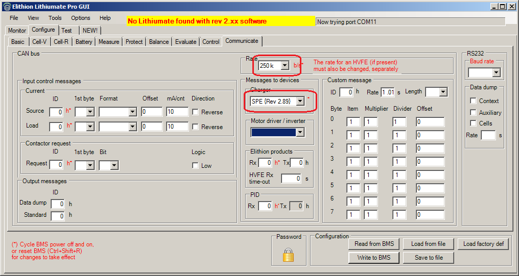
Note that the ElCon CAN rate is 250 kHz, so you will have to program the BMS to also work at 250 kHz.
Message generated by Lithiumate BMS
| PGN
| Repetition rate
| Data length
| Data page
| PDU format
| PDU specific
| Default priority
| Source Address
| ID (*)
| Byte 0
| Byte 1
| Byte 2
| Byte 3
| Byte 4
| Byte 5
| Byte 6
| Byte 7
|
| 58868
| 1 s
| 8
| 0
| 1 (0x01)
| 229 (0xE5)
| 6
| 244 (0xF4)
| 0x1806E5F4
0x1806E7F4
0x1806E8F4
0x1806E9F4
| Voltage [100 mV]
| Current [100 mA]
| Control (1)
| (n.a.)
0x00
| (n.a.)
0x00
| (n.a.)
0x00
|
| MSB
| LSB
| MSB
| LSB
|
(*) Select "ElCon E4", "ElCon E7", "ElCon E8" or "ElCon E9" in the GUI.
(1) Control byte:
| 7
| 6
| 5
| 4
| 3
| 2
| 1
| 0
|
| -
| -
| -
| -
| -
| -
| -
| 0 = On; 1 = Off
|
Message generated by ElCon charger
| PGN
| Repetition rate
| Data length
| Data page
| PDU format
| PDU specific
| Default priority
| Source Address
| ID
| Byte 0
| Byte 1
| Byte 2
| Byte 3
| Byte 4
| Byte 5
| Byte 6
| Byte 7
|
| 20709
| 1 s
| 8
| 0
| 63 (0x3F)
| 80 (0x50)
| 6
| 229 (0xE5)
| 0x18FF50E5
| Voltage [100 mV]
| Current [100 mA]
| Status (1)
| (n.a.)
0x00
| (n.a.)
0x00
| (n.a.)
0x00
|
| MSB
| LSB
| MSB
| LSB
|
(1) Status byte *:
| 7
| 6
| 5
| 4
| 3
| 2
| 1
| 0
|
| -
| -
| -
| Communication:
1 = CAN reception time-out (> 10 s since last message)
| DC voltage:
1 = reverse battery polarity detected
| AC voltage:
1 = not within acceptable range
| Charger temperature:
1 = over temperature
| Hardware:
1 = hardware failure
|
(*) If any status flag is set, the charger will not charge
Note: Elektro Automatik no longer manufactures these chargers, and the latest version of the Elithion software no longer supports them.
With rev 1.33 to 2.35, if enabled, the Lithiumate interfaces seamlessly with the a Elektro Automatik chargers.
| ID
| Bytes
| Period
| Byte 0
| Byte 1
| Byte 2
|
| 0x614
| 3
| 1 s
| 0x36 (1)
| 0x11 (1)
| 0x11 (1)
|
| 0x614
| 3
| 1 s
| 0x33 (2)
| MSB (2)
| 00
|
| 0x615
| 1
| 1 s
| 0x47 (3)
|
|
Notes:
- Turn on remote control, turn on output
- Maximum DC output current [%]
- 0 to 100 % (0x00 to 0x64) of nominal current setting of charger
- BMS configuration is required
- Request actual values
The BMS master looks for battery current information on the CAN bus from the charger.
| ID
| Bytes
| Byte 0
| Byte 1
| Byte 2
| Byte 3
| Byte 4
| Byte 5
| Byte 6
|
| 0x616
| 7
| 0x47
|
| MSB (1)
| LSB (1)
|
|
Notes:
- Actual battery current, as percent of nominal current, + = into battery
The Lithiumate interfaces seamlessly with a single Eltek Valere charger.
See the Eltek Valere page page for details.
| BMS rev
| Default CAN speed
| Byte order
| Read current from charger
|
| 2.89+
| 250 kbps *
| Big endian
| No (requires current sensor)
|
*) Both the BMS and the charger can be configured for a different speed
| ID
| Bytes
| Rate
| Byte 0
| Byte 1
| Byte 2
| Byte 3
| Byte 4
| Byte 5
| Byte 6
| Byte 7
|
| 0x6C1
| 8
| 1 s
| 0x00
| 0x00
| 0x00
| 0x00
| 0x00
| 0x00
| CCL [%] (1)
| 0x00
|
Notes:
- The BMS cannot control the CC and CV settings; those have to be configured into the charger;
all the BMS can do is to reduce the current with respect to that setting
- The CC setting in the charger must have the same value as the Peak Charging Current setting in the BMS (Configure tab / Protect tab / Charging box / Peak curr. field)
- Charge Current Limit, relative to configured Constant Current setting in the charger [%]
e.g.: if the charger Constant Current setting is 200 A: 0x00 = no current; 0x32 = 50 % of CC setting = 100 A; 0x64 = 100 % of CC setting = 200 A
0xFF if charging is disabled
When configured for a Zivan SG3 charger with RE software, a Lithiumate with rev 2.40 and later sends the following messages.
Notes:
- Multi-byte values are big-endian: the MSB (Most Significant Byte) is in the lower numbered data byte (the right most byte in the following tables)
- Number of data bytes: 8
- Select a CAN speed of 125 kHz (default, but both the BMS and the charger can be configured for a different speed)
Notes:
| ID
| Byte 0
| Byte 1
| Byte 2
| Byte 3
| Byte 4
| Byte 5
| Byte 6
| Byte 7
|
| 0x6C1
| 0x00
| 0x00
| 0x00
| 0x00
| 0x00
| 0x00
| CCL (1)
|
| 0x776
| Current limit setpoint (2)
| Voltage limit setpoint (3)
| 0x00
| 0x00
| Battery minimum voltage (4)
|
- [0.1%] Variable value, based on CCL, 0~1000 = 0 to 100 % of Peak Charge Current setting
- [100 mA] Fixed value, based on Peak Charge Current setting
- [100 mV] Fixed value, based on Max Cell Voltage setting
- [100 mV] Fixed value, based on Min Cell Voltage setting
If you wish to receive the charging current from the charger (as opposed to using a current sesnor),
configure the BMS to receive it as the "source" current ("Communicate" tab of the GUI).
- ID: 0x2A4 (assuming the default node ID of 9)
- 1st byte: 2
- Format: high low (big endian)
- Offset: 0
- ma/cnt: 100
- Direction: reverse (checked)
The Lithiumate Pro, with rev 2.05 and later, interfaces seamlessly with a MES / CEBI TIM series motor inverter.
See the MES / CEBI TIM page for details.
The Lithiumate Pro, with rev 2.07 and later, interfaces seamlessly with a NetGain WarpDrive DC motor controller.
See the NetGain page for details.
The Lithiumate Pro, with rev 2.18 and later, interfaces seamlessly with a TM4 Neuro, and, through that, to a TM4 motor inverter.
See the TM4 page for details.
When configured for a SMA Sunny Island inverger, a Lithiumate with rev 2.38 and later sends the following messages.
Important note: Under various conditions, the SMA Sunny Island inverger does not obey the BMS: it continues charging despite the BMS telling it not to.
The battery MUST include a way to disable charging, directly and independently. We recommend a protector switch that controls charging and discharging independently.
Notes:
- Multi-byte values are little-endian: the MSB (Most Significant Byte) is in the higher numbered data byte (the right most byte in the following tables)
- Period: 1 s
- Number of data bytes: 8
- Select a CAN speed of 500 kHz
- Turn off all other CAN messages: the Sunny Island is unable to handle unexpected messages on the CAN bus
| ID
| Byte 0
| Byte 1
| Byte 2
| Byte 3
| Byte 4
| Byte 5
| Byte 6
| Byte 7
|
| 0x351
| Battery charge final voltage [100 mV]
| Charge current limit [100 mA]
| Disharge current limit [100 mA]
| Battery discharge final voltage [100 mV]
|
| 0x355
| SoC [%]
| 0x00
| SoH [%] (5)
| 0x00
| 0x00
| 0x00
| 0x00
| 0x00
|
| 0x356 (6)
| Battery voltage [10 mV]
| Battery current [100 mA], (7)
| Battery temperature [0.1 °C], signed
| 0x00
| 0x00
|
| 0x35A
| Fault flags 0 (1)
| Fault flags 1 (2)
| Fault flags 2 (3)
| 0x00
| Warning flags 0 (1, 4)
| Warning flags 1 (2, 4)
| Warning flags 2 (3, 4)
| 0x00
|
Notes:
- Warning and flags, byte 0:
- Bit 7:
- Bit 6: High temperature
- Bit 5:
- Bit 4: Low cell voltage
- Bit 3:
- Bit 2: High cell voltage
- Bit 1:
- Bit 0: General
- Warning and flags, byte 1:
- Bit 7:
- Bit 6: Over-current (either direction)
- Bit 5:
- Bit 4: Low temperature (warning only)
- Bit 3:
- Bit 2: High temperature
- Bit 1:
- Bit 0: Low temperature (warning only)
- Warning and flags, byte 2:
- Bit 7:
- Bit 6: Ground isolation (warning only)
- Bit 5:
- Bit 4: (not used)
- Bit 3:
- Bit 2: Contactors (fault only)
- Bit 1:
- Bit 0: Charge over-current
- Odd numbered bits are the opposite of the adjacent even bits: if bit 0 is set, bit 1 is clear, and viceversa.
- Instead of SoH, the Sunny Island expects the actual relative capacity
- Added in Rev 2.87; the Sunny Island logs these data but does not do anything with them
- Signed. Discharging current is positive