|
|
index  reference reference  tools tools
Tools
Recommended tools to install and operate the BMS

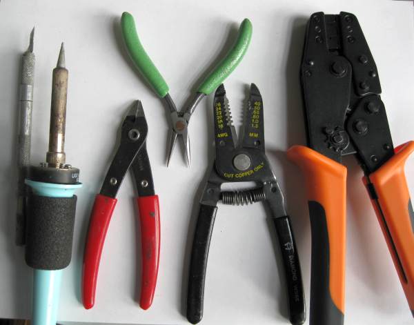
Some of the tools used in installing a BMS
- Professsional 24 AWG open barrel crimper, required
- Exacto knife
- Soldering iron
- Needle nose pliers
- Wire stripper for 24 AWG wire
- Extraction tools:
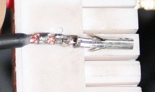
An improperly crimped socket, done using the wrong tools and incorrect stripping length.
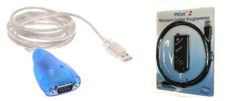
Some of the tools used in programming a BMS
- USB-RS232 serial dongle, required to program the Lithiumate™ BMS controller if your computer doesn't already have a serial port:
- PIC programmer, optional, allows you to back-up and / or duplicate the settings from / to a Lithiumate™ BMS controller:
Materials:
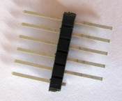
- 0.1" pitch pin strip, 0.26" on each end, breakable: Digikey
Construction:
- Break off a group of 6 pins
- Clip one of the pins off, just on one side
For your reference, the pin out is:
- Vpp (this is the pin closest to the white Control connector)
- Vdd (5 V)
- Vss (Gnd)
- PDAT (data)
- PCLK (clock)
Materials:
- 0.1" pitch pin strip, 5 pins
- 0.1" pitch pin strip, 6 pins
- Five wires, 4" length, yellow, red, black, white, green
- 1/8" heat shrink tubing
Construction:
- Solder the wires to the 6 pin connector:
- yellow
- red
- black
- white
- green
- none
- Install 10 pieces of 3/8" long heat shrink tubing on the 5 wires, two per wire
- Solder the wires to the 5 pin connector:
- red
- white
- green
- yellow
- black
- Slip the heat shrink tubing on the soldered ends of the pins, and heat shrink

Programmer adapter diagram
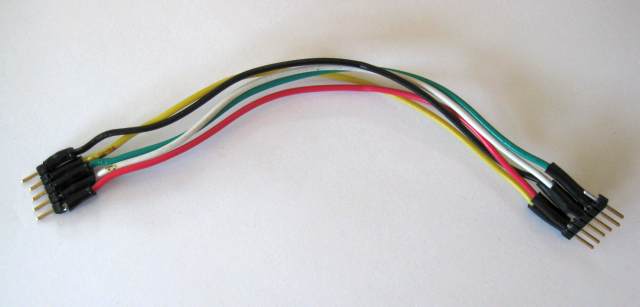
Programmer adapter cable
- Connect the programmer to the BMS controller with the adapter cable
- programmer side: 6 pin connector, yellow wire on pin marked by a triangle
- BMS controlelr side: 5 pin connector, red wire in pin 1 (closest to white connector)
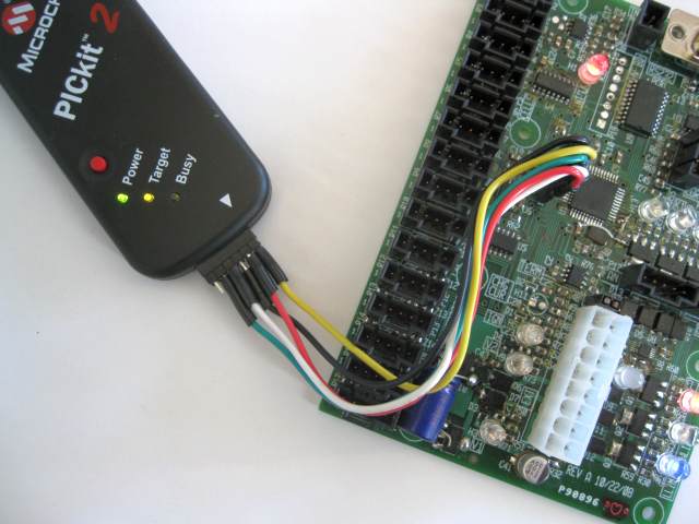
PICKit 2 programmer connected

|
|


