|
Lithiumate™ Manual |
|
Lithiumate™ Manual |
|
Tips Tips for using the BMS 
The negative and positive end cell boards normally include a right angle, 2-pin connector. This connector extends above the barrel of the ring terminal, making it the tallest component. In applications where that is a problem, you may move the connector off the board, so that it sits lower and it no longer cause an interference. 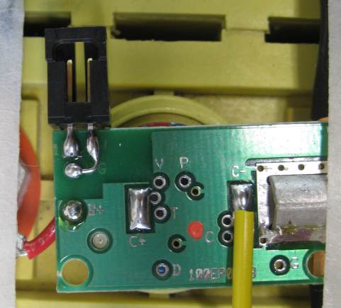
Cell board connector off the board. Having the connector off the board is not as secure, so adding some epoxy may be a good idea. Alternatively, you may want to consider using 2 short wires to move the connector offthe board all together. A Lithiumate with HVFE can be configured to perform a test of the pack's isolation from chassis just before turning on the contactors. This test has some limitations: it is only performed once before turing on, and it lasts just 10 ms, which will make it fail if there is a significant capacitance between the battery terminals and chassis. An external controller can force the HVFE to perform an isolation test through PID messages on the CAN bus, at any time, and make it last as long as required to charge up the capacitance between the battery terminals and the chassis. To do so, follow the steps listed in the table "To test pack isolation, contactors off" on the 3rd sheet of the PID list spreadsheet. The BMS can work with batteries that are either positively or negatively grounded. The BMS is optically isolated from the cell boards and so, it doesn't care how the battery is grounded. For older rev BMS controllers (Rev 0.96 and older), you can use a programmer and a Windows computer to read and write the settings from your distributed BMS' EEPROM. (Newer BMS controllers have a built in back-up function, so there's no need for a programmer to do a back-up.) This can be useful as a back-up, or to quickly duplicate settings from one BMS controller to others.
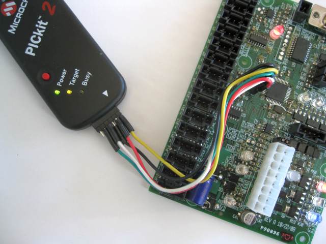
PICKit 2 programmer connected
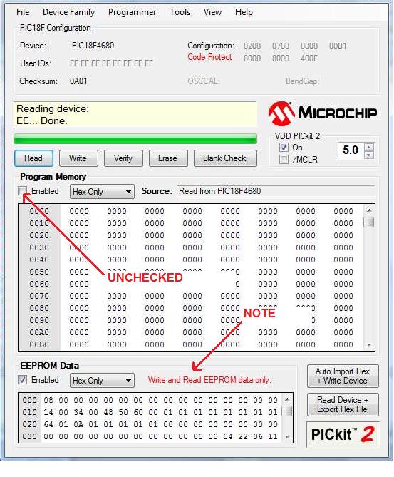
PICKit 2 programmer window
You can build your own WiFi hotspot, using these instructions, courtesy of Peter Chave. Note: Elithion cannot offer absolutely any tech support on this solution.
| ||
© 2008~2025 Elithion™, LLC. All rights reserved, except where noted by CC mark. Page published on May 07 2024.
The Elithion brand and the 'ə' (upside down 'e') logo are Trademarks of Elithion LLC. Graphic design by morninglori