|
|
index  install install_remote_hvfe install install_remote_hvfe
Install - Remote HVFE
Installation instructions for the 2HR0xxxX Remote HV Front End.

Unfortunately, we do not have the resources to teach all of our clients proper assembly procedures, which are essential for a successful project.
What we can do is pass along this info to you:
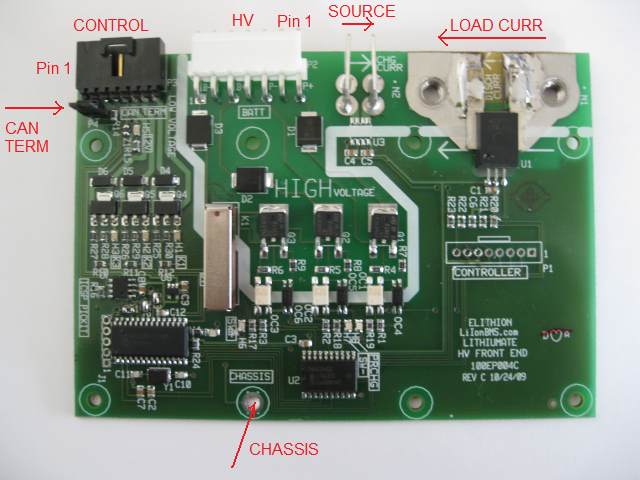
One possible wiring approach is shown here:
Suggested wiring schematic.
The lines on the white, 7-pin connector of the HVFE are isolated, giving you flexibility on wiring it as appropriate for your application.
- B+ and B- terminals of the HVFE have two functions:
- Detecting loss of isolation between the battery pack and the chassis ground
- Measuring the pack voltage (available on starting from Rev D hardware / Rev 1.03 software, units manufactured after April 2010)
- If you wish to do isolation testing, connect the B+ and B- terminals of the HVFE to the B+ and B- terminals of the battery
- If you do not wish to do isolation testing, and you are using contactors between the battery and the load, you can connect the B+ and B- terminals of the HVFE on either side of the contactors
- On the battery side if you want know the battery voltage when the contactors are open
(and also if you want to test for battery voltage presence before turning on the contactors, for example, to make sure that the main fuse is OK and the safety disconnect is in place)
- On the load side if you want to know the load voltage when the contactors are open
Respect polarity of the B+ and B- terminals of the HVFE (though no damage occurs if you connect them the opposite way)
- P+ and P- terminals of the HVFE are available to measure the voltage across the precharge resistor, to detect the presence of precharging current
- Respect polarity of the P+ and P- terminals of the HVFE (though no damage occurs if you connect them the opposite way):
current must flow in the precharge resistor from the end connected to the P+ terminal, to the end connected to the P- terminal
- The precharge resistor may be placed on either side of the precharge relay
- The precharge circuit may be placed on the positive or the negative battery side
- If you don't connect the P+ and P- wires, the BMS will use instead the load current sensor to detect the precharge current
- If the HVFE includes one or two current sensors, you may use it / them to measure the source or load current
- Route the source/load current through the appropriate sense terminals
- The current may be sensed either before or after the contactors
- The current may be sensed either on the positive or the negative battery terminal
- Respect polarity (but, if you wired it backwards, you can reverse the direction through programming)
This connector is connected to the low voltage (typically the aux 12 V supply).
This connector has 3 functions:
- Power in
- CAN bus
- Contactor drive output (optional)
| On PCB
| Mate
| Pin-out
|
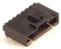
Molex C-Grid CL, 0.1" pitch
7-pin male right angle header
|
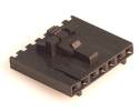
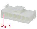
Female housing, locking: 50-57-9407 DK:WM2905-ND
Crimp socket, 22-24 AWG gold: 16-02-0103 DK:WM2512-ND
|
Female connector, wire entry side
|
| #
| Name
| Type
| Function
| Notes
|
| 1
| GND
| Pwr
| Ground (power and signal)
|
|
| 2
| CANL
| Bus
| CAN bus low
|
|
| 3
| CANH
| Bus
| CAN bus high
|
|
| 4
| 12Vin
| Pwr
| Power in
|
|
| 5
| K3
| Out
| Contactor drive
| Open drain
|
| 6
| K2
|
| 7
| K1
|
- Use wire between 24 and 22 AWG (between 0.2 and 0.5 mm2)
- Strip the wires 0.075"e / 2 mm
- Crimp the wires into the C-Grid female terminals
- Slip the terminals into the C-Grid housing, until they snap in place
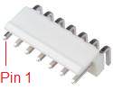
- Pin 1 is marked on the housing with a triangle
This connector is connected to the high voltage (connected to the battery).
This connector has 3 functions:
- Detects the presence of voltage across the precharge resistor (if you have one)
- Wire the precharge resistor if you want to stop precharge when the voltage across the resistor drops to a low value, or you want to test the proper operation of the precharge circuit and contactors
- Use pins 1 and 3
- Detects the presence of voltage across the battery terminals
- Wire the battery terminals if, before turning on the contactors, you want to make sure that battery voltage is present
- Use pins 5 and 7
- Detects any current path between the battery and the chassis
- Wire the battery terminals if, before turning on the contactors, you want to make sure that the battery is isolated from the chassis
- Use pins 5 and 7 and make sure the PCB (2HR0xxxB) or case (2HR0xxxE) is grounded to the chassis
| #
| Name
| Type
| Function
| Notes
|
| 1
| P+
| In
| Precharge positive end
If the resistor is in series with the positive lead, this is the resistor lead towards the battery
|
To sense the precharge current (the voltage drop across the precharge resistor).
|
| 3
| P-
| In
| Precharge resistor negative end
If the resistor is in series with the positive lead, this is the resistor lead towards the load
|
| 5
| B+
| In
| Battery positive terminal
|
To sense leaks to chassis due to loss of isolation, and presence of battery voltage.
|
| 7
| B-
| In
| Battery negative terminal
|
The pin numbers are on the housing (on rev C PCBs the '1' on the silk screen is on the wrong side)
When installed, pin # 1 is closest to the center of the board.
Odd-numbered pins are unused to improve high voltage rating.
The resistor pins are isolated from the battery pins; therefore, the precharge resistor may be placed on either battery polarity, and on either side of a contactor.
Inputs are protected against polarity reversal.
- Use wire rated for the battery voltage, such as 300 V, 600 V or 100 V; if unavailable, run the wire through tubing for additional insulation
- Use wire between 22 and 18 AWG (between 0.5 and 1 mm2)
- Strip the wires 0.1"e / 2 mm
- Crimp the wires into the VHR female terminals
- Slip the terminals into the VHR housing, until they snap in place
The HVFE can be used to measure the load current (50, 100 or 200 A).
| On PCB
| Mate
|
|
M5 threaded insert
|
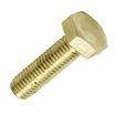
Size 10 or M5 ring terminal; M5 bolt
|
- Use an appropriate wire size for the average current (peak current can be higher)
- Use wire rated for the battery voltage, such as 300 V, 600 V or 100 V; if unavailable, run the wire through tubing for additional insulation
- For 25 A use 14 AWG / 2.5 mm2 wire or greater
- For 50 A use 10 AWG / 6 mm2 wire or greater
- For 100 A use 6 AWG / 16 mm2 wire or greater
- For 200 A use 1/0 AWG / 50 mm2 wire or greater
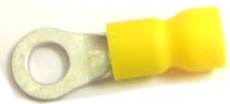
- Use straight ring terminals for the M5 bolts used on the HVFE
- Stud size: 5 mm, 10 Gauge (1/4" will work but will be sloppy)
- Max OD: 0.5" / 12.7 mm
- Crimp size: appropriate for wire used; the Outer Diameter of terminals for large wire sizes is more than 0.5", so you may need to file them down
- If the terminal is not insulated, use heat shrink to insulate
- Some suggested parts:
- 14 AWG: Tyco 36160, 34161, 32960, 320574, 51864-2, 31903, 324533, 696423-6, 53418-1, 51864-9, 320630; 3M MVU14-10RK, 94728, 94729; Panduit PV14-10R-M, PV14-10R-C, Molex 19070-0102, 19073-0087, 19070-0090
- 12 AWG: 3M 94741, MVU10-10RK; Tyco 696424-6, 324918, 2-36161-3, 32883, 50845-2, 35364, 36161, 34854, 35109; Molex 19073-0170
- 10 AWG: 3M 94741, MVU10-10RK; Tyco 696424-6, 324918, 2-36161-4, 32883, 50845-2, 35364, 36161, 34854, 35109; Molex 19073-0170
- 8 AWG: Tyco 52263-1, 52263, 324043
- 6 AWG: Tyco 52042-4, 53119-1, 324046, 52265
- 4 AWG: (not insulated) Tyco 33114, Molex 19193-0273
- 2 AWG: (not insulated, 0.62" OD) Tyco 330301
- 1/0 AWG: (not insulated, 0.87" OD) Tyco 160000
- Strip the wires as appropriate for the crimp barrel of the terminal
- Crimp the wires into the terminals
- 2HR0xxxE: open the case of the HVFE (4 screws)
- Remove the two M5 bolts for teh high current sensor
- Place the M5 bolts through the washer and through the terminals, then screw into the PCB assembly, so that the discharging current flows from the left terminal to the right terminal (from the terminal closest to the end of the board, to the terminal closest to the white connector)
- If placing it on the positive wire: connect the right terminal to the red wire going to the load '+' input, and the left terminal to the red wire going to the battery '+' terminal
- If placing it on the negative wire: connect the left terminal to the black wire going to the load '-' input, and the right terminal to the black wire going to the battery '-' terminal
- Tighten the M5 bolts 50 inch-pounds / 6 Nm
- 2HR0xxxE: close the case of the HVFE (4 screws)
The HVFE can be used to measure the source current (5 A or 20 A).
| On PCB
| Mate
|
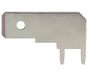
Right angle 1/4" male quick connect tab terminal
|
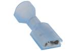
1/4" female quick connect tab terminal
Red: 18-22 AWG; blue: 14-16 AWG
|
- Use an appropriate wire size for the average current (peak current can be higher)
- Use wire rated for the battery voltage, such as 300 V, 600 V or 100 V; if unavailable, run the wire through tubing for additional insulation
- For 5 A use 22 AWG / 0.5 mm2 wire or greater
- For 10 A use 20 AWG / 0.5 mm2 wire or greater
- For 20 A use 16 AWG / 1.5 mm2 wire or greater
- Use female quick-connect tab terminals
- Size: 1/4" x 0.032", fully insulated straight
- For 16 AWG wire use 14-16 AWG terminals, blue insulation
- 3M: 94820, FDI14-250C, MNU14-250DFIK
- Tyco 3-350820-2, 3-520408-2, 3-520117-2, 3-520141-2
- Molex 19003-0044, 19003-0040, 19003-0040, 19002-0024
- For smaller wire use 18-22 AWG terminals, red insulation
- 3M: 94803, FDI18-250C, MNU18-250DFIK
- Tyco 2-520184-4, 2-520184-2, 2-520264-2, 2-520407-2
- Molex 19002-0001, 19005-0001, 19003-0001
- Strip the wires as appropriate for the crimp barrel of the terminal
- Crimp the wires into the terminals
- Slip the terminals into the tabs in the HVFE, so that the charging current flows from the right terminal to the left terminal (from the terminal closest to the white connector, to the terminal closest to the high current connectors)
- If placing it on the positive wire: connect the right terminal to the red wire going to the charger '+' output, and the left terminal to the red wire going to the battery '+' terminal
- If placing it on the negative wire: connect the left terminal to the black wire going to the charger '-' output, and the right terminal to the black wire going to the battery '-' terminal
Mount the PCB assembly with 8 screws or bolts, with a maximum size of 4-40 / M3.
The HVFE can be used to measure battery insulation before turning in the contactors. In that case, the hole marked "CHASSIS" must be grounded reliably.
Mount the case with 4 screws or bolts, with a maximum size of 6-32 / M3.5. Use flat washers. Tighten with appropriate torque.
The HVFE can be used to measure battery insulation before turning in the contactors. In that case, the case must be grounded reliably.
- Install the case on a grounded metal chassis
- Remove the paint on one of the case's mounting holes, both top and bottom, and any paint on the corresponding spot on the chassis, so that bare metal of the case will touch bare metal on the chassis
- Install the case, paying particular attention that the bolt used in the grounding hole makes reliable connection to the chassis
The HVFE contains a switchable terminator resistor for the CAN bus. By default, the termination is in place.
To remove the termination, or place it back in:
- For rev C PCBs:
- 2HR0xxxE: open the case of the HVFE (4 screws)
- Find the small, black, shorting jumper, just behind the control connector
- For CAN termination, place the jumper on the 2 pins; for no termination, place it on only 1 pin
- 2HR0xxxE: close the case of the HVFE (4 screws)
- For rev D PCBs:
- Find the small, black, shorting jumper, just next to the control connector (accessible from the outside of the case in a 2HR0xxxE)
- For CAN termination, place the jumper on the bottom 2 pins; for no termination, place it on the top 2 pins
By default, the HVFE is preset to communicate with the BMS controller as it is preset at the factory.
Should you need to, here are instructions to reprogram the settings
Usually, the HVFE uses a low current sensor (5 or 20 A) to measure the source current, and a high current sensor (50, 100 or 200 A) to measure the load current.
It may be possible to modify the HVFE to use the high current sensor (50, 100 or 200 A) to measure the source current.
Please see these modification instructions.

|
|