
You MUST provide a way for the BMS to shut down the source (charger), and the load, DIRECTLY!
Otherwise, your cells are NOT PROTECTED, and will not be balanced.
BOTH GROUND PINS MUST BE WIRED TO THE SUPPLY!
We strongly recommend that you use prewired HD harnessed from Elithion.
If you choose instead to make your own harnesses, you must be able to do so with high quality assembly skills.
Unfortunately, we do not have the resources to teach all of our clients proper assembly procedures, which are essential for a successful project.
What we can do is to pass along this info to you:
This connector is for low power signals.
NOTE PIN NUMBERS AND TAB ORIENTATION!
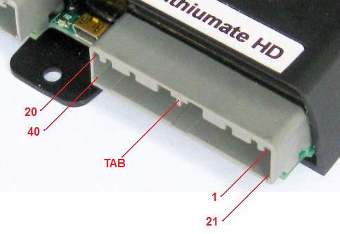
Control connector pin numbers and orientation.
| #
| Name
| Type
| Function
| Notes
|
| 1
| GND
| Gnd
| Ground
| Return for source current sensor
|
| 2
| SRCCUR
| Inputs
| Source current
| Analog input to measure current from the source / charger
|
| 3
| 5V
| Pwr out
| 5 V supply
| To power source current sensor
|
| 4
| GND 6
| Gnd
| Bank ground
| Return for TX and RX for bank 6; also for shield, do not terminate shield at far end
|
| 5
| TX 6
| Banks
| Transmit out bank 6
| To most positive cell in the bank; red wire
|
| 6
| RX 6
| Banks
| Receive in bank 6
| To most negative cell in the bank; white wire
|
| 7
| GND 4
| Gnd
| Bank ground
| Return for TX and RX for bank 4; also for shield, do not terminate shield at far end
|
| 8
| TX 4
| Banks
| Transmit out bank 4
| To most positive cell in the bank; red wire
|
| 9
| RX 4
| Banks
| Receive in bank 4
| To most negative cell in the bank; white wire
|
| 10
| GND 2
| Gnd
| Bank ground
| Return for TX and RX for bank 2; also for shield, do not terminate shield at far end
|
| 11
| TX 2
| Banks
| Transmit out bank 2
| To most positive cell in the bank; red wire
|
| 12
| RX 2
| Banks
| Receive in bank 2
| To most negative cell in the bank; white wire
|
| 13
| GND 0
| Gnd
| Bank ground
| Return for TX and RX for bank 0; also for shield, do not terminate shield at far end
|
| 14
| TX 0
| Banks
| Transmit out bank 0
| To most positive cell in the bank; red wire
|
| 15
| RX 0
| Banks
| Receive in bank 0
| To most negative cell in the bank; white wire
|
| 16
| GND
| Gnd
| Signal ground
| Use a separate wire from power ground, to avoid errors in analog readings.
|
| 17
| CANL
| CAN
| CAN Bus low
|
|
| 18
| TERM
| CAN
| CAN Bus termination
|
|
| 19
| SOC
| Lin out
| State Of Charge analog out
| Analog voltage: 5 V = 100 % full, down to 0 V = empty
|
| 20
| DCL
| Lin out
| Discharge Current Limit
| Analog voltage: 5 V = no limit, down to 0 V = no discharging current allowed.
|
| 21
| GND
| Gnd
| Ground
| Return for load current sensor
|
| 22
| LODCUR
| Inputs
| Load current
| Analog input to measure current to the load
|
| 23
| 5V
| Pwr out
| 5 V supply
| To power load current sensor
|
| 24
| GND 7
| Gnd
| Bank ground
| Return for TX and RX for bank 7; also for shield, do not terminate shield at far end
|
| 25
| TX 7
| Banks
| Transmit out bank 7
| To most positive cell in the bank; red wire
|
| 26
| RX 7
| Banks
| Receive in bank 7
| To most negative cell in the bank; white wire
|
| 27
| GND 5
| Gnd
| Bank ground
| Return for TX and RX for bank 5; also for shield, do not terminate shield at far end
|
| 28
| TX 5
| Banks
| Transmit out bank 5
| To most positive cell in the bank; red wire
|
| 29
| RX 5
| Banks
| Receive in bank 5
| To most negative cell in the bank; white wire
|
| 30
| GND 3
| Gnd
| Bank ground
| Return for TX and RX for bank 3; also for shield, do not terminate shield at far end
|
| 31
| TX 3
| Banks
| Transmit out bank 3
| To most positive cell in the bank; red wire
|
| 32
| RX 3
| Banks
| Receive in bank 3
| To most negative cell in the bank; white wire
|
| 33
| GND 1
| Gnd
| Bank ground
| Return for TX and RX for bank 1; also for shield, do not terminate shield at far end
|
| 34
| TX 1
| Banks
| Transmit out bank 1
| To most positive cell in the bank; red wire
|
| 35
| RX 1
| Banks
| Receive in bank 1
| To most negative cell in the bank; white wire
|
| 36
| GND
| Gnd
| Signal ground
| Use a separate wire from power ground, to avoid errors in analog readings.
|
| 37
| CANH
| CAN
| CAN Bus high
|
|
| 38
| TERM
| CAN
| CAN Bus termination
|
|
| 39
| CGND
| CAN
| CAN Bus ground
|
|
| 40
| CCL
| Lin out
| Charge Current Limit
| Analog voltage: 5 V = no limit, down to 0 V = no charging current allowed.
|
This connector is for high power signals.
NOTE PIN NUMBERS AND TAB ORIENTATION!
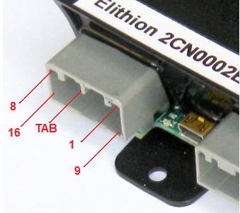
Power connector pin numbers and orientation.
| #
| Name
| Type
| Function
| Notes
|
| 1
| FLT
| O.D. out
| Fault
| Open collector, polarity selectable in software. Activated in case of fault.
|
| 2
| K3
| O.D. out
| Negative contactor coil (-)
| Open collector
|
| 3
| K2
| O.D. out
| Positive contactor coil (-)
| Open collector
|
| 4
| K1
| O.D. out
| Precharge relay coil (-)
| Open collector
|
| 5
| FAN
| O.D. out
| Low power fan drive / drive for fan relay
| Grounded when cooling is required
|
| 6
| V+S
| Pwr in
| Power in from source
|
The BMS is powered by voltage at either terminal (uses isolating diodes).
V+L must be powered whenever the load is on, and only then.
V+S must be powered whenever the source is on, and only then.
For example, in a BEV or PHEV application, V+L is powered by Ignition, V+S is powered whenever the vehicle is plugged into AC power.
In a HEV application, V+S is powered by the ignition.
In a UPS application, V+S is powered whenever there's AC power, and V+L is powered all the time.
If only one power source is possible, use V+S.
Which input powers the BMS selects which current sensor is used. If both are powered simultaneously, the current reading may double.
|
| 7
| V+L
| Pwr in
| Power in from load
|
| 8
| V+
| Pwr out
| Full voltage utility supply
|
Voltage present when BMS powered through either V+ line.
May be used to power equipment such as loggers, remote controllers.
|
| 9
| LLIM
| O.D. out
| Low Limit
| Open collector, polarity selectable in software. Activated when the most discharged cell's voltage is too low
|
| 10
| HLIM
| O.D. out
| High Limit
| Open collector, polarity selectable in software. Activated when the most charged cell's voltage is too high.
|
| 11
| PGND
| Gnd
| Power ground
| Use a separate wire from signal ground, to avoid errors in analog readings.
|
| 12
| FAN PWM
| Dig out
| Variable Duty Cycle Pulse Width Modulation
| 0% DC for no cooling, up to 100% DC for full cooling
|
| 13
| PGND
| Gnd
| Power ground
| Use a separate wire from signa ground, to avoid errors in analog readings.
|
| 14
| Cont. Req.
| Dig in
| Contactor request
| Requests that contactors be on. For vehicle applications, connected to the Ignition line (off when ignition goes off).
|
| 15
| PGND
| Gnd
| Power ground
| Use a separate wire from signal ground, to avoid errors in analog readings.
|
| 16
| V+
| Pwr out
| Full voltage utility supply
|
Voltage present when BMS powered through either V+ line.
May be used to power equipment such as loggers, remote controllers.
|
Use this circuit if driving contactors from the Lithiumate HD Master.
Contactor circuit.
BOTH GROUND PINS MUST BE WIRED TO THE SUPPLY!
This controller has 2 separate grounds.
- Signal ground: low current, reference for digital and analog signals
- Power ground: carries the high current for power devices: fan driver and contactor coil drivers
Both of these grounds must be connected to the negative of the low voltage supply (the 12 V nominal power supply, DC-DC converter or battery that powers the BMS), each through a separate wire.
These grounds are connected to each other on the BMS controller by a small resistor.
Grounding of the BMS.
The negative of the low voltage supply (which is connected to the signal and power grounds) may or may not be connected to the earth or chassis, as required by the application.
In general, for safety reasons, the negative of the high voltage battery (the Li-Ion pack that is managed by this BMS) should not be connected to these grounds.
Yet, if safety is not an issue, as far as the Elithion BMS is concerned, it is OK to do so.
BOTH GROUND PINS MUST BE WIRED TO THE SUPPLY!
This controller has 2 separate power inputs
- Source: on when the power source is on, such as a battery charger
- Load: on when the battery load is on, such as a motor driver
The BMS is on when there's voltage on either of these inputs.
See the specifications for the allowable voltage range and the supply currents.
Power to and from the HD master.
The BMS provides 2 power outputs for external devices:
- V+: powered whenever either power input is powered, at the highest voltage of the two
- 5V: powered at the same time, but sourcing 5 V
See the specifications for the maximum current available from these outputs.
There are 7 Open Drain Outputs on the power connector
- FLT: Fault
- HLIM (High limit): battery unable to accept charge
- LLIM (Low limit): battery unable to accept discharge
- K1: precharge relay coil drive
- K2: positive contactor coil drive
- K3: negative contactor coil drive
- FAN: cooling fan drive
Open drain outputs.
Each of these outputs is either open (clamped to 42 V) or connected to the power ground, depending on the state they are reporting.
- With a pull-up resistor to the 5 V supply, they can be used as TTL or CMOS logic outputs
- They can drive medium power DC loads directly, such as relays
- See the specifications for the maximum sinking current and maximum open circuit voltage for these outputs.
Note that the polarity (active open or active grounded) is programmable. See the programming instructions.
There are 3 linear (analog) outputs on the control connector
- SOC (State Of Charge)
- CCL (Charge Current Limit)
- DCL (Discharge Current Limit)
Signal outputs.
- These outputs produce a voltage in the range from 0 V to 5 V, according to the state of the condition they report
- They can drive light loads, such as the inputs of Analog to Digital converters
- They can drive resistors of no less than 5 kOhm, such as throttle pots
- See the specifications for their output resistance, and maximum voltage for these outputs.
There is one digital PWM output on the control connector
- PWM (Pulse Width Modulation)
- This is a CMOS output (0 or 5 V), with a high frequency square wave of variable duty cycle, from 0% (always at 0 V: no fan) to 100 % (always at 5 V: full fan speed)
- It can drive a light load, such as the inputs of a power buffer
- It cannot drive a fan directly
There are 3 signal inputs on the control connector
- Source Current: a linear (analog) input
- Load Current: a linear (analog) input
- Contactor request: a digital input
The control connector also has ground and 5 V outputs to power current sensors.
Signal inputs.
- The Source Current input can be driven by a charger that puts out a linear voltage proportional to the charging current
- This input responds to voltages in the range from 0 V to 5 V, but it is protected against voltages outside this range
- The Contactor Request input can be driven by the 12 V ignition line in a vehicle
If the application includes a CAN bus, the CAN bus lines can be connected to it.
CAN bus connections.
- The CAN bus is isolated (it is not referenced to the supply ground)
- Normally it is not necessary to connect the CAN ground
- If the master is at the end of the CAN bus, terminate the bus by connecting the each CAN line to one of the TERM lines.
Connect a USB mini-B cable to this port and to a computer running the Lithiumate GUI application.
The battery pack should be divided into between 1 and 8 banks or at least 3 cells each.
A cell board is mounted on each cell.
The two end boards in each bank are connected to the control connector.
The Master sends data to the cell boards ("TX") and receives back data ("RX").
| Name
| Type
| Function
| Wire color
| Notes
|
| TX
| Out
| Transmit out
| Red
| To most positive cell in the bank
|
| GND
| Gnd
| TX return
| Black
|
| Shield
| Common for both TX and RX
| -
| Do not terminate at other end
|
| Gnd
| RX return
| Green
| To most negative cell in the bank
|
| RX
| In
| Receive in
| White
|
If you wish to make your own harnesses, you may use the compoents and tools listed below.
| Elithion PN
| Description
| Manuf & PN
|
| EKV3416UA
| 16-way plug housing
| JAE MX34016SF1
|
| EKV3440UA
| 40-way plug housing
| JAE MX34040SF1
|
| EKV3403ST
| 22 AWG crimp socket
| JAE M34S75C4F1
|
| EKV3404ST
| 20 AWG crimp socket
| JAE M34S75C4F2
|
| n.a.
| Hand crimping tool, 20 AWG
| JAE CT150-1-MX34
|
| n.a.
| Hand crimping tool, 22 AWG
| JAE CT150-2-MX34
|
| n.a.
| Extraction tool
| JAE ET-MX34-1
|