|
Lithiumate™ Manual |
|
Lithiumate™ Manual |
|
index Install - Configurable SOC display Installation, wiring and configuration instructions for the 6DS0000E display. 
These are the installation and configuration instructions for the configurable Elithion SOC display, 6DS0000E. Unfortunately, we do not have the resources to teach all of our clients proper assembly procedures, which are essential for a succesful project. What we can do is to pass along this info to you:
This SOC display is designed to fit in a 2 inch (5 cm) hole in a panel. A U-shaped bracket presses against the panel and holds the display in place. 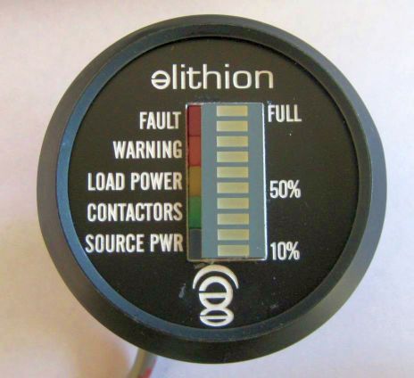
Round SOC display The SOC display is connected to the CAN bus and a 12 V power source through a 4-conductor cable. 
CAN display connections.
In plug-in vehicles, power the display from the V+ output of the BMS Master (which is powered whether the ignition is on or the vehicle is plugged into the wall). The CAN bus requires 2 each 120 Ohm resistors, one at each end of the bus. The BMS Master includes a 120 Ohm resistor (which can optionally be disconnected). The SOC display also includes a CAN termination resistor, which may be disconnected by cutting the small wire loop on the back of the case. If the BMS Master and the SOC display are the only other device on the CAN bus, you need to enable the CAN termination resistors on the BMS Master and leave the loop on the Display in place. If there are additional devices on the CAN bus, then terminators must be placed at the 2 ends of the bus. If the display is not at one end of the bus, disconnect its termination resistor by cutting the loop. At power up, the display indicates the configured CAN speed by lighting a single LED for less than 1 second:
Afterward, it turns on all the LEDs. As soon as it receives a CAN message, the LEDs will switch to normal operation. If there are no messages, after about 10 seconds the display will reset itself, and start again by displaying the CAN speed. The CAN speed may be reconfigured in the field in one of 2 ways:
To reconfigure with a jumper:
| |||||||||||||||||||||||||||
© 2008~2025 Elithion™, LLC. All rights reserved, except where noted by CC mark. Page published on May 07 2024.
The Elithion brand and the 'ə' (upside down 'e') logo are Trademarks of Elithion LLC. Graphic design by morninglori